Practical GD&T: Sphericity Measurement – Basic Concepts
Sphericity is used in engineering dimensioning & tolerancing to control the geometric form of any object which is wholly or partly spherical. Sphericity is a measure of how far the actual feature surface deviates from the ideal case of a perfect sphere.
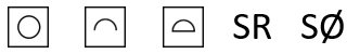
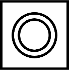
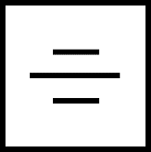
GD&T symbol
There is no dedicated symbol specifically for sphericity in either the ISO or ASME GD&T standards. Typically, sphericity will either be defined using a roundness callout, or a profile of a line or surface. A profile of a line or surface can control form, size and optionally position with datums. Roundness will control form only; it is possible to use an additional spherical diameter or spherical radius callout to control feature-of-size (FOS).
Drawing callout
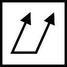
The two examples below show a spherical form being controlled in two different ways, using the symbols above:
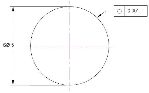
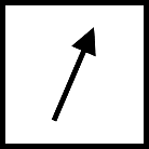
In this first example, for a full sphere, the size is controlled by a spherical diameter (SØ) on the left, while the sphericity is controlled by the circularity feature control frame on the right. Without the SØ constraint, the scale of the sphere is not constrained, and any size ball could pass inspection provided it met the 0.001 roundness requirement. It may be desirable to have a more relaxed tolerance for scale (for instance in the case of matched ball bearings, where the important requirement is for all balls to be the same size, not necessarily any one exact size). The above notation decouples the tolerance on sphericity from the tolerance on size.
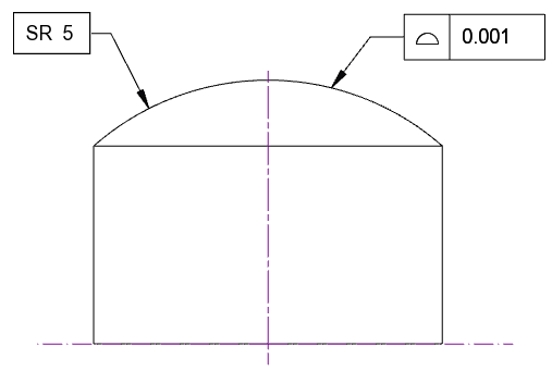
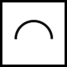
In the second example, a spherical segment caps the end of a cylindrical post. Here, the spherical radius is given as a basic dimension on the left, but actual tolerance on form and size is controlled by the profile of a surface on the right. Either of these controls may be appropriate, depending on what exactly is required for a particular functional part.
Where can sphericity be applied?
Sphericity only applies to a very limited number of geometries; either true spheres/balls, partial spheres (e.g. a blend radius between two cylindrical shafts), or partial spherical recesses.

What standards apply to GD&T sphericity?
See the ASME standard 14.5-2018, where sphericity is covered as a special case of circularity. Under the ISO standards, see ISO 1101, where sphericity of a partial sphere is addressed with the use of a profile-of-a-surface control.
Sphericity, roundness, profile of a line and profile of a surface
As is already clear from the standards, there are several ways to control a spherical feature in GD&T. Any of roundness, profile of a line and profile of a surface may be appropriate. For a full 100% sphere, the part is necessarily purely a free-standing ball (e.g. a ball bearing) and so no datums can be relevant. For a partial spherical feature appearing on a more complex overall part, remember that the use of roundness will not control the position or scale of the sphere, so if the sphericity, size and location are all important, consider instead profile of a line or profile of a surface with suitable datums.
What about aspheres?
In practical examples, especially in the domain of optics, one shape often encountered is the asphere. “Asphere” literally means “not a sphere”, and this term covers a wide variety of shapes, which typically possess rotational symmetry and may even appear to the eye to be “sphere-like” in form. They are mathematically different, often following a revolved profile defined by a more complex mathematical function representing a base radius and higher order equation superimposed. As such, a sphericity control is not a good choice for reporting deviation on these shapes. Owing to the particular requirements for an aspheric lens, the most critical form error is the deviation from this higher order equation and the allowable peak-to-valley error (P-V) is specified on drawings.
Interested in fast and accurate measurement of precision components with an optical CMM? Try the OmniLux range of coordinate measuring machines.
Overview of GD&T
For an overview of GD&T including the other symbols, please see our practical guide.

Special case: Sphericity