| Type | Control | Symbol(s) | Applicable Standards | Description |
| Form | Roundness or Circularity | 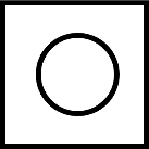 | ASME Y14.5 to current (2018)
ISO 12181 | A two-dimensional measure, comparing a part or measured profile to a perfect circle |
| Cylindricity | 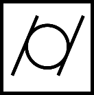 | ASME Y 14.5 to current (2018)
ISO 12180 | A three-dimensional measure, comparing a part or measured profile to a perfect cylinder |
| Straightness |  | ASME Y 14.5 to current (2018)
ISO 12780 | A measure in two or three dimensional space, reporting deviation from a perfect straight line for a feature (e.g. a part surface or an axis) |
| Flatness | 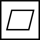 | ASME Y 14.5 to current (2018)
ISO 12781 | A three-dimensional measure, comparing a part or measured profile to a perfect 2D plane |
| Profile | Profile of a Line | 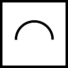 | ASME Y 14.5 to current (2018)
ISO 1660 | A measure along a 1D profile in 2D or 3D space, reporting deviation from the ideal design intent (which can be any freeform path) |
| Profile of a Surface |  | ASME Y 14.5 to current (2018)
ISO 1660 | A measure over a 2D surface in 3D space, reporting deviation from the ideal design intent (which can be any freeform surface) |
| Orientation | Parallelism | 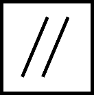 | ASME Y 14.5 to current (2018)
ISO 1101 | A measure of how parallel a line, axis or plane is to another line, axis, surface datum / datum system |
| Perpendicularity | 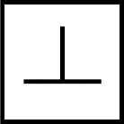 | ASME Y 14.5 to current (2018)
ISO 1101 | A measure of the deviation from a 90° orientation between a line, axis or plane and some other line/axis/surface datum/datum system. |
| Angularity | 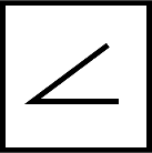 | ASME Y 14.5 to current (2018)
ISO 1101 | An orientation measure which can control any required angle between |
| Runout | Circular Runout | 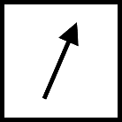 | ASME Y 14.5 to current (2018)
ISO 1101 | A control which limits local change in surface position as a part is rotated about an axis. Each local measure is independent of each other measure. |
| Total Runout |  | ASME Y 14.5 to current (2018) | A control which limits total change in surface position across an entire surface simultaneously as a part is rotated about an axis. |
| Location | Concentricity | 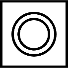 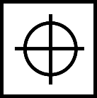 | ASME Y14.5 up to 2009 (withdrawn 2018)
ISO 1101 | A control which ensures the ‘centre’ points of a profile lie on a defined datum point or axis; this requires a clear definition for the centre points. Note that position control is now used instead in the ASME standard. |
| Symmetry |   | ASME Y14.5 up to 2009 (withdrawn 2018)
ISO 1101 | A control to ensure the mid-points of a nominally symmetric profile lie in the datum line/plane defining the mirror symmetry Note that position control is now used instead in the ASME standard. |
| Position |  | ASME Y 14.5 to current (2018)
ISO 5458 | Controls the location of a point, centre axis or centre plane of a feature, relative to a datum feature or (for a feature pattern) relative to other pattern instances |
| Feature of Size | no symbol | ASME Y 14.5 to current (2018)
ISO 14405, 14406 | Controls the absolute size of a part within tolerances. May/may not influence other controls depending on standards used. Can be used to define an axis/midplane for datum referencing. |
| Roughness |  | ASME B 46.1, ISO 1302 & related standards | Controls local surface profile at the smaller scale (short spatial wavelength) |
| | | | |
| Special Cases | | | | |
| Sphericity | | Covered as a special case of circularity or form profile; application-specific standards also exist (e.g. ISO 7206 for implants) | A three-dimensional measure comparing a part of measured profile to a perfect sphere (ball) |


