Practical GD&T: Circular Runout – Basic Concepts
There are two variations of runout control in geometric dimensioning and tolerancing (GD&T): Circular runout and total runout; both are checking a similar mechanical behaviour, but circular runout is slightly simpler and less restrictive than total runout. In this article, we focus on circular runout; a separate article covers total runout.
GD&T symbol
As with many of the controls in GD&T, a circular runout check is indicated with a tolerance frame, or feature control frame in the CAD model or on the blueprints. Note that unlike some of the simpler form controls (e.g. roundness) a runout control cannot be included without a datum; the datum must be an axis of rotation, and even if this is very obvious for a part or assembly it should be explicitly defined on the CAD/drawing.
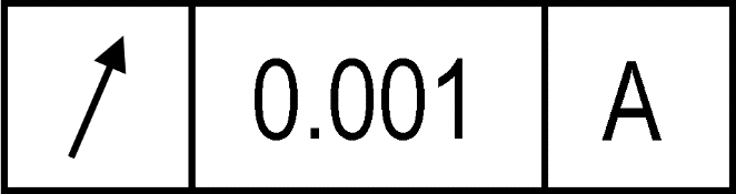
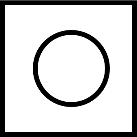
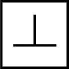
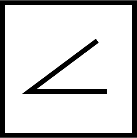
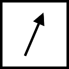
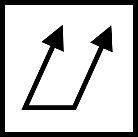
Note that the symbols for circular and total runout are similar. The symbol is designed to represent the needle on a typical dial test indicator (DTI) gauge. The head of the arrow is normally filled but may sometimes be a wireframe outline. Circular runout shows a single DTI gauge ‘needle’ (circular runout in one location, while total runout (which inherently must be measured in multiple places) includes two representative ‘needles’:
Circular runout: 
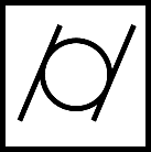
Total runout: 
Drawing callout
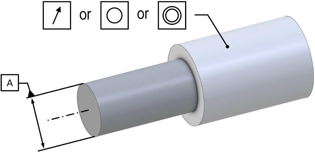
As already noted, a runout control on a drawing or CAD model always requires the axis of rotation to be indicated. The illustrations below show a minimal example of a circular runout check.

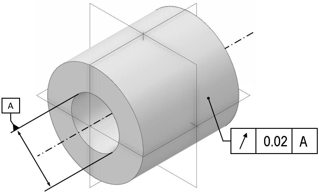
The tolerance zone for this control at any given location is two concentric circles, which must be centred on the axis of the datum ‘A’ at the point where it intersects the inspection plane. The size of the two circles is not constrained; they may be enlarged or reduced, but the difference in radius between the two must be equal to the numerical tolerance stated on the control.
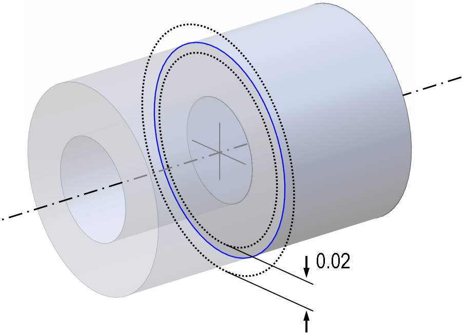
This means that the tolerance zone for circular runout is similar to the tolerance zone for a circularity check, except that the circles cannot freely translate. This is very different to the case for total runout; see the total runout article for more details.
An important point to note is that the result of the runout check will also depend upon exactly how the axis of rotation is defined and measured. As an exaggerated example, consider the part below, with two cylindrical surfaces forming the axis on either side of the feature being checked for runout. A runout check could be applied either to the outer cylindrical face, or to either of the planar faces:

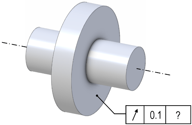
Above: for this part, a runout control is valid for the cylindrical face as radial runout(left) and the end faces as axial runout (right)
Here a ‘?’ has been inserted where the datum reference should be, to indicate that there are three possible choices for the datum; the left cylinder only, the right cylinder only, or a common datum formed by measuring both surfaces. The correct choice depends heavily upon the functional application of the part; it is not necessarily always best to use a common datum.
Consider the case where the two cylinders should be aligned, but are not, as shown below. It is now possible to get different results for runout, depending which datums are measured and where; compare the figures below:
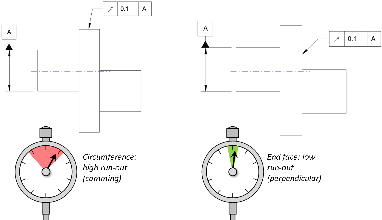
Above: using just one side for datum would give a high runout for the cylindrical face (left), but a low runout for the planar end face which is close to perpendicular to the axis (right)
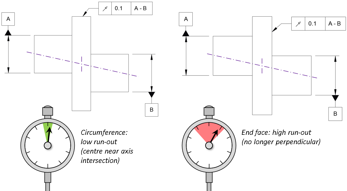
Above: using a common datum (A-B) for the runout check now reduces the runout reported for the cylindrical circumference (depending on where it is measured), but increases the runout for the end-face (again depending where it is measured).
It is important to note that the result of these checks would depend on the location(s) where the datum is measured and also the location(s) where the circular runout check is performed. Consider carefully if additional details should be added to your drawing to avoid any ambiguity on these points.
Circular runout applications
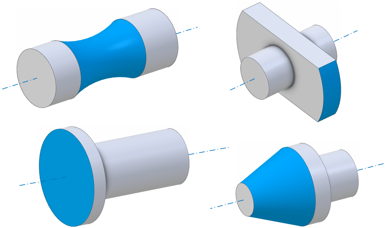
Runout is typically intended for parts or assemblies with an axis of rotation. But it is a geometric control and could be applied to a non-rotating part which nonetheless has a rotational axis of symmetry. The control can apply to any feature which has rotational symmetry that should be aligned with that axis – for instance cylindrical features, spherical features, conical features and planar features where the plane normal is parallel to the axis of rotation. A few examples are shown below. Note the ISO standard does specifically note that runout could be applied to a partial feature (incomplete revolution), although most practical examples that are encountered have a full 360° profile sweep.
GD&T standards for runout
The two forms of runout are covered in both the US and international standards; see ISO 1101 and ASME Y14.5.
Circular runout or total runout
For more on when to choose circular runout and when to choose total runout, see the article on <total runout> where the difference is discussed in more detail.
Runout, roundness, and concentricity
It is common to encounter designs where runout, roundness and concentricity might all apply. Consider a geometry with two cylinders of different diameter (e.g. a stepped dowel pin):
A few variations can be considered:
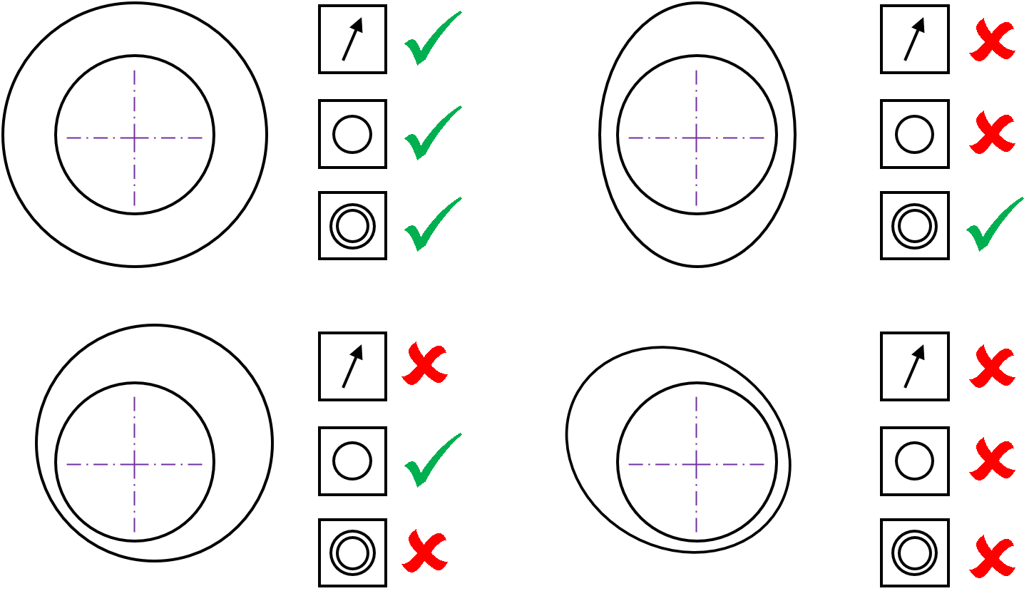
As the four cases show, the part can pass a concentricity check without being round, or pass a roundness check without being concentric. Only if it is both round and concentric would a runout check be passed.
Obviously, this is a simplistic theoretical example; concentricity can be difficult to assess and is no longer prescribed by the ASME standards (see <concentricity> article), and there are many cases where more than one GD&T control may be used with different tolerances (for instance where a part needs to be highly round, but the concentricity/position is less critical).
Interested in fast and accurate measurement of precision components with an optical CMM? Try the OmniLux range of coordinate measuring machines.
Overview of GD&T
For an overview of GD&T including the other symbols, please see our practical guide.

Special case: Sphericity