Practical GD&T: Cylindricity Measurement – Basic Concepts
Cylindricity is used in GD&T to control the form of a nominally cylindrical shaft or hole. It imposes a requirement that the form of that feature cannot deviate from the form of an ideal cylinder by more than a certain permitted tolerance. Cylindricity applies to the full form of a 2D surface in 3D space.
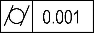
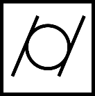
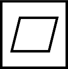
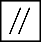
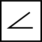
GD&T symbol
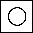
Cylindricity is applied by including a feature control frame (FCF) on the drawing or in the 3D CAD model. The symbol is differentiated from the roundness control by two oblique lines either side of a circle. Cylindricity is a basic form control and does not need extra datums or other information to be used; it applies to a feature independently. It does always need to include a numerical tolerance alongside the symbol in appropriate drawing units.
Drawing callout
The cylindricity feature control frame may be seen both on a 2D print and within a 3D CAD model, as shown below.
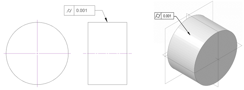
Note that unless the drawing indicates otherwise, the cylindricity applies to the entire surface. Be aware of this if the surface has poorly defined edges featuring a tapered chamfer or blend/fillet radius. (It may be wise to define a zone within which the cylindricity control applies, to remove ambiguity).
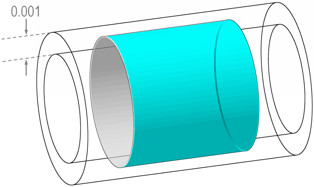
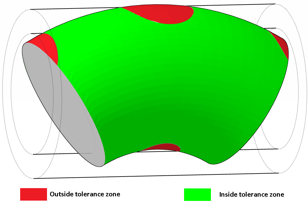
For a normal cylindricity control, the tolerance zone would therefore look like the below illustration; two concentric cylinders form the upper and lower tolerance bounds; it must be possible for all parts everywhere on the full 2D surface in 3D space to fit between these two cylinders.
A part which is fully contained between these two concentric cylinders is a pass; consider this cylinder, with a bent axis but still fully within the tolerance zone (obviously, greatly exaggerated).

On the other hand, if a part cannot be fully contained between the two surfaces, the part is a fail. Consider the same cylinder bent somewhat more; now, no matter how the part is translated/rotated, or how the cylinders are scaled whilst maintaining the same radius separation, it will never be possible to fully enclose the cylindrical face within the tolerance zone.
The cylindricity requirement applies across the full face, so the measurement equipment used should ideally measure 100% coverage of the surface. This is often not possible in practice.
A note on ‘per-unit-length’ cylindricity: although a per unit condition on a cylindricity control is possible, it is not considered standard practice. If applying the control in this way, treat it as a non-standard measurement and ensure that your manufacturing and inspection personnel have clearly communicated the expectation of how this will be assessed.
Where can cylindricity be applied?
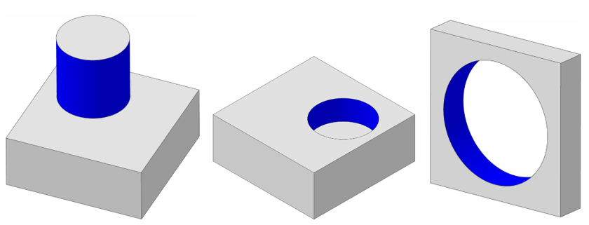
Of all the basic GD&T form controls (roundness, straightness, flatness, and cylindricity), cylindricity is perhaps the most constrained, and so has the most focused applicability. In practice, this will only apply to either positive material cylindrical forms (e.g. shafts, pins), or negative material zones (e.g. holes and recesses)
What standards apply to GD&T cylindricity?
For more details, see ISO 12180, and ASME 14.5-2018, Section 8.
Cylindricity vs roundness
Roundness is less constraining than cylindricity. A roundness requirement applied to a nominally cylindrical shaft would require each individual roundness scan in isolation to be circular but puts no constraint on the relative position between those individual scans from one to the next. A cylindricity check would effectively add the additional requirement that the centres of each roundness circle must all line along the same straight line. So a path traced around for instance the major axis of a torus could conform to roundness, but not to cylindricity.
Cylindricity vs profile of a surface
It would be possible to use profile of a surface to achieve control to a cylindrical form. However, cylindricity puts no additional constrain on the absolute size and position of that cylindrical form relative to any other geometry of the part. Profile of a surface by contrast can be used to lock down the cylindrical form and size and position / orientation, if this is required. If the only requirement is for a shaft to be cylindrical, regardless of size, then a basic cylindricity control is clearer and simpler for anyone reading the prints to follow.
Interested in fast and accurate measurement of precision components with an optical CMM? Try the OmniLux range of coordinate measuring machines.
Overview of GD&T
For an overview of GD&T including the other symbols, please see our practical guide.

Special case: Sphericity