Practical GD&T: Perpendicularity Measurement – Basic Concepts
Perpendicularity is one of three angular (orientation) controls within GD&T, and is used in both the ISO and ASME standards. Along with angularity and parallelism, it allows a designer to specify that a feature (e.g. a planar surface or an axis) needs to be nominally at 90 degrees to another feature (the datum) within a certain allowable tolerance. As such, and as with the other orientation controls, it is a relative control, so the datum being referenced must also be clearly defined
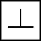
GD&T symbol
As with the other orientation controls, the tolerance frame or feature control frame for perpendicularity must have both a numerical value for tolerance and a datum, as shown:

Note that numerical value is not an angle, it is a unit of linear distance, and defines the width of the tolerance zone (for instance, for a flat surface, it would indicate two parallel plane separated by the linear distance shown)
Drawing callout
Because the datum is an integral part of the perpendicularity tolerance, any drawing including a perpendicularity callout is only complete if the drawing also includes a definition of the datum:

The above constraint on a cube might seem at first glance to be specifying perpendicularity in an ‘all over’ sense, but this is not a correct use of the control frame. It is necessary to define which other face of the cube is the reference point; constraints can then be applied variously to the other faces. The below would be a standards-compliant way to control just one face relative to the datum:

But note that this only controls the relationship between those two faces. To fully control the orientation of all faces on the cube would require additional datums and GD&T tolerances (a combination of parallelism and perpendicularity).
Using this simple example of a single tolerance control on a cube, the tolerance zone in this case would simply be two parallel planes, as shown:

As the illustration on the right shows, if the datum surface ‘A’ is not at the expected nominal angle, then this will also rotate the angle of the two planes which form the tolerance zone.
Note that the parallel planes can be freely translated to fit the profile. They are not at a fixed location and do not control position at all – perpendicularity is purely an orientation control.
In the above example, there is an inherent flatness requirement for the surface being inspected. In some cases (e.g. perpendicularity of an axis), this may be an inherent straightness requirement. It is not uncommon to see a feature with a stricter requirement for straightness/flatness, and a more relaxed orientation requirement (for instance perpendicularity).
As with all controls, be careful when including a perpendicularity control drawing that it is correctly annotated in the drawings. For instance, consider the below applied to our example cube:

Applied to the width of the cube like this, the perpendicularity now applies not to both sides, but rather to the mid-plane between them. This means that it is possible for neither face to be at 90° to datum A, but the part to pass inspection, as long as the two faces have roughly equal and opposite slope, so that the mid-points at all cross sections would fall within a tolerance band, as shown:

A consequence of this is that perpendicularity can be used to control axis features where no point on the surface is actually perpendicular; for instance, consider a cone on a flat planar face. The face of the cone is not at 90° to the plane, but a perpendicularity constraint can be applied to the axis of the cone. GD&T constraint like this start to become more difficult to measure without either custom gauging, or else measurement machines capable of capturing the full surface profile.

Applications
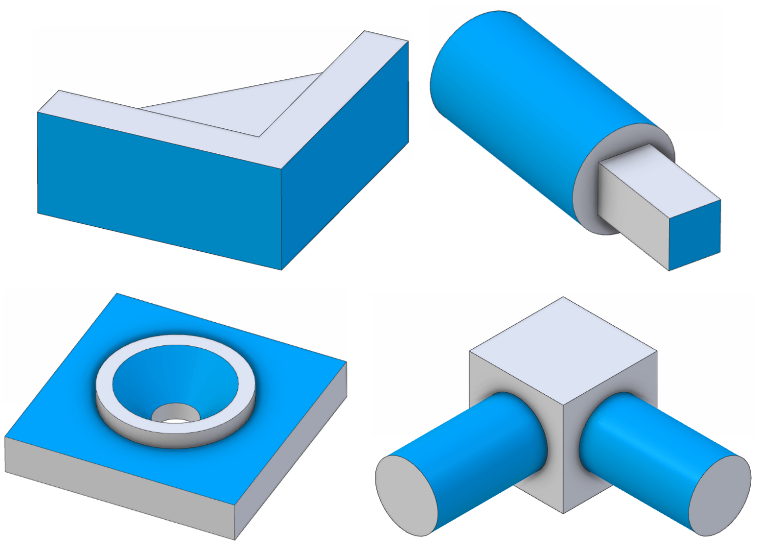
As has been noted, perpendicularity can apply to both faces, but also axes and derived median geometry. This means that quite a wide range of geometries may be eligible to be controlled with a perpendicularity call-out; a few generic example models are shown below. Note that this is a relative control between two features, so pairs of faces/features are highlighted on the 3D geometries shown.
Standards
Perpendicularity does not have its own stand-alone standard, but is covered, with examples, within both ISO 1101 and ASME Y14.5. Please refer to those respective standards for more details and examples.
Perpendicularity vs angularity
Perpendicularity and parallelism are both special cases (more constrained) of the more general angularity constraint, and it is possible to exclusively use angularity for all these cases, with a stipulated angle (using a basic dimension) of either 0° or 90°, as required. It is worth considering what will be easiest and clearest for anyone reading off the engineering drawings, but the standards leave both options open for possible use.
Perpendicularity vs profile of a line / profile of a surface
The profile-of-a-line and profile-of-a-surface controls are able to constrain angularity of all forms (including parallelism and perpendicularity). However these controls also restrict the translational position, not just orientation, and so they suit a different set of situations to the pure orientation controls. Consider whether for a specific situation the design requirement is exclusively to control orientation, or whether positional tolerance is also important.
Interested in fast and accurate measurement of precision components with an optical CMM? Try the OmniLux range of coordinate measuring machines.
Overview of GD&T
For an overview of GD&T including the other symbols, please see our practical guide.






Special case: Sphericity

